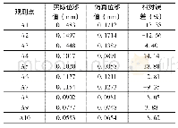
《表3 120℃时LTCC基板表面试验与仿真位移对比Tab.3 Comparison of LTCC substrate surface displacements from the test and
 提示:宽带有限、当前游客访问压缩模式
本系列图表出处文件名:随高清版一同展现
《热循环载荷下LTCC基板焊接组件结构仿真分析与试验对比研究》
将得到的LTCC基板表面实际位移值与仿真位移值进行比较,如表3所示。其中,测量得到的实际位移值与仿真位移值的相对误差计算公式为:
| 图表编号 | XD0030615900 严禁用于非法目的 |
|---|---|
| 绘制时间 | 2019.01.05 |
| 作者 | 张怡、王习武、邓超、王天石、仇原鹰 |
| 绘制单位 | 中国电子科技集团公司第二十九研究所、西安电子科技大学机电工程学院、中国电子科技集团公司第二十九研究所、中国电子科技集团公司第二十九研究所、西安电子科技大学机电工程学院 |
| 更多格式 | 高清、无水印(增值服务) |


