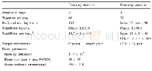
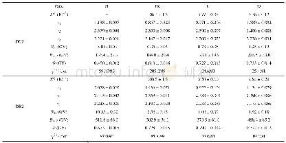
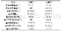
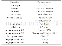
《Table 1 The main processing parameters of injection molding》
 提示:宽带有限、当前游客访问压缩模式
本系列图表出处文件名:随高清版一同展现
《"Distribution of α-, β-, and γ-Phases in a Multi-flow Injection-molded Hierarchical Structure"》
An MFVIM device,which can offer a periodic shear field,was developed to prepare i PP samples.Its schematic drawing and working principle have been described in our previous studies[41].Compared with that in our previous work,in the current experiment,vibration pressure was applied only one or two times,and the time interval between two vibrations was sufficiently long to form a spherulite layer.For convenience,the samples subjected to vibration pressure once and twice are designated as VIM I and VIM II,respectively.CIM was also used under similar thermal conditions to prepare samples for comparison.The main processing parameters are illustrated in Table 1.As shown in Fig.1,the sample has rectangular geometry with a dimension of 59,60 and 3 mm.The molding gate is in fan-shape with an end dimension of 59 and 5 mm.The thickness of gate is larger than that of cavity,so as to achieve relatively homogeneous flow.To investigate morphological evolution,the samples were divided into three zones along the flow direction.In addition,one half-width of each specimen was separated into eight layers along the thickness direction for X-ray measurements.
| 图表编号 | XD0020171300 严禁用于非法目的 |
|---|---|
| 绘制时间 | 2018.06.01 |
| 作者 | Da-Shan Mi、Feng-Yi Hou、Man Zhou、Jie Zhang |
| 绘制单位 | College of Polymer Science and Engineering,State Key Laboratory of Polymer Materials Engineering,Sichuan University、College of Polymer Science and Engineering,State Key Laboratory of Polymer Materials Engineering,Sichuan University、College of Polymer Scie |
| 更多格式 | 高清、无水印(增值服务) |


