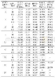
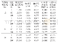
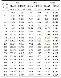
《Tab.2 Specific results of different radial location of circumferen-tial grooves》
Figure 8 shows the relative velocity vector and entropy distribution at the inlet of groove for CGCT No.2 and No.3at near-stall point.It can be seen from the figure that,for the treated casing diffusers,the fluid in the tip of diffuser passage is sucked into the groove,which shrinks the area of the tip fluid separate region,and the fluid velocity in the tip region increases.The entropy value at the inlet section of CGCT No.2 is greater than CGCT No.3,which has the similar results with cross sections in Figure 7.
| 图表编号 | XD0017594800 严禁用于非法目的 |
|---|---|
| 绘制时间 | 2018.12.26 |
| 作者 | 陈雪飞、秦国良 |
| 绘制单位 | School of Energy and Power Engineering, Xi'an Jiaotong University、School of Energy and Power Engineering, Xi'an Jiaotong University |
| 更多格式 | 高清、无水印(增值服务) |
 提示:宽带有限、当前游客访问压缩模式


