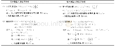
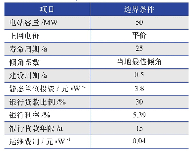
《表3 玻璃窑池模型边界条件》
qm is mass flux at boundary;qm,batch is the mass flux of bath at the feed inlet;qm,glass is the mass flux of molten glass at the outlet;U is velocity vector;T is temperature;qT is heat flux at solid surface;hwall is heat transfer coefficient at wall surf
根据第1节中所述玻璃熔窑GFM数值模型,对图2所示浮法玻璃熔窑进行GFM建模。熔窑GFM模型中主要边界条件如表3、表4所示,其中,玻璃液拉引量qm,batch=6.366 kg/s;配合料投料量qm,batch=7.591 kg/s,配合料入窑温度Tbatch=30℃;环境温度T∞=30℃;窑体外表面自然对流散热系数hwall=(8.38+0.001 67Twall)W/(m2·K);燃料分配及蓄热室热效率如表1所示;模型耦合边界(GM–CM coupling)的实施如1.3节所述;流固耦合热边界(Fluid–solid coupling)描述了流固界面处温度与热通量均相等;池底鼓泡每支气量为12.5 L/min。
| 图表编号 | XD0051639300 严禁用于非法目的 |
|---|---|
| 绘制时间 | 2019.02.01 |
| 作者 | 彭寿、陈淑勇、马立云、陶天训、金良茂 |
| 绘制单位 | 浮法玻璃新技术国家重点实验室中建材蚌埠玻璃工业设计研究院有限公司、浮法玻璃新技术国家重点实验室中建材蚌埠玻璃工业设计研究院有限公司、浮法玻璃新技术国家重点实验室中建材蚌埠玻璃工业设计研究院有限公司、浮法玻璃新技术国家重点实验室中建材蚌埠玻璃工业设计研究院有限公司、浮法玻璃新技术国家重点实验室中建材蚌埠玻璃工业设计研究院有限公司 |
| 更多格式 | 高清、无水印(增值服务) |
 提示:宽带有限、当前游客访问压缩模式


