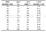
《Table 2 Geometry parameters of the composite vessel》
 提示:宽带有限、当前游客访问压缩模式
本系列图表出处文件名:随高清版一同展现
《考虑自增强影响的Ⅲ型复合材料气瓶连续损伤模拟及渐进失效分析(英文)》
Fig.4 shows the finite element mesh model of the vessel.The geometry parameters of the composite vessel are listed in Table 2.Only half of the vessel is modeled by consideration of the symmetry of the vessel structure,and appropriate load conditions and symmetric boundary are specified for the vessel.In this finite element model,the aluminium liner and the composite layers are modeled using the reduced integration element C3D8R,enhanced hourglass control,and distortion control.With the element size 2 mm×2 mm,8832 bulk elements are included in the aluminium liner,and 109 760 bulk elements with the element size 0.9 mm×0.9 mm are included in the composite layers.The aluminium liner and the composite layers are tied together.In order to balance the numerical error and convergence,the viscous stabilization method with viscous constant 0.001 is adopted to obtain the ultimate load capacity of the composite vessel effectively.The aluminium liner is considered to be isotropic andelastic-plastic.The stress-strain curves for aluminium obtained from experiments are shown in Fig.5.The elastic modulus and Poisson’s ratio of the aluminium are 70 GPa and 0.33,respectively.The yield strength is about 298 MPa.Material parameters for transversely isotropic composite layers are the same as the values in Table 1.
| 图表编号 | XD0046971500 严禁用于非法目的 |
|---|---|
| 绘制时间 | 2019.01.03 |
| 作者 | Bin-bin LIAO、Dong-liang WANG、Li-yong JIA、Jin-yang ZHENG、Chao-hua GU |
| 绘制单位 | Institute of Process Equipment, Zhejiang University、Institute of Process Equipment, Zhejiang University、First Aircraft Institute of Aviation Industry Corporation、Institute of Process Equipment, Zhejiang University、State Key Laboratory of Fluid Power and M |
| 更多格式 | 高清、无水印(增值服务) |


