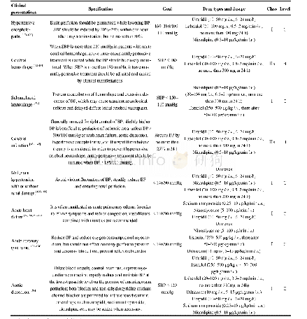
《Table 5 Procedural specifications for automatic girth welding of the hot-induction-bend and line pi
 提示:宽带有限、当前游客访问压缩模式
本系列图表出处文件名:随高清版一同展现
《Automatic girth welding and performance evaluation of the joints of hot-induction-bend and line pipes with different wall thickness》
Table 5 presents the procedural specifications for automatic girth w elding of the hot-induction-bend and line pipes.In all of the w elds,w e applied approximately the same w elding procedural specifications.First,to avoid w elding flaw s,w e used a w ire brush or mechanical method to clean an area that w as w ithin a distance of 25 mm around the pipe end.To release w ater into the pipe section surface,the pipe sections must be preheated to no higher than 80℃.During w elding,the interpass temperature must become no more than 150℃.We applied straight draw ing w elding in the root and hot w elds w ith a fairly low heat input,w hereas w e applied single-layer sw ing w elding in the filler and cap w elds.We determined the sw ing w idth based on the remaining bevel w idth to ensure complete fusion and to ensure that there is no burn through.For the root w eld,w e used a PIW56(CPP900-IW56)automatic internal w elding machine w ith an internal alignment clamp,w hereas for the filler and cap w elds,w e used a PAW3000(CPP900-W2)external automatic w elding machine for filler and cap w elds.
| 图表编号 | XD004636100 严禁用于非法目的 |
|---|---|
| 绘制时间 | 2018.06.30 |
| 作者 | CAO Neng |
| 绘制单位 | Research Institute,Baoshan Iron & Steel Co.,Ltd. |
| 更多格式 | 高清、无水印(增值服务) |


