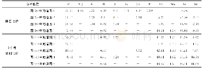
《Table 1 Spectrum and energy distribution of the solar radiation test chamber》
 提示:宽带有限、当前游客访问压缩模式
本系列图表出处文件名:随高清版一同展现
《Change in Surface Microstructure and Properties of PTFE after Solar Radiation and its Mechanism》
According to related Standards for Solar Radiation Tests,such as MIL-STD-810D/E505 of USA,DEFSTAN 00353-03 of Europe and GJB150.7A-2009of China,the experimental scheme is designed as follows:all of the discal and filmy samples were divided into 4 groups,one group was as-obtained PTFE,the other three groups were radiated by simulated sunlight for 4,8 and 12 days,respectively.The test equipment is Q-SUN XE-3-HSC type Solar Radiation Simulator,its schematic diagram is shown in Fig.1.The radiation source is made up of 3 parallelfixed Xe lamps,their energy and spectrum distribution are shown in Table 1.The test parameters were as follows,radiation intensity was 1 120 W/m2,test temperature was 55℃and the humidity was 70%RH,respectively.
| 图表编号 | XD0043330200 严禁用于非法目的 |
|---|---|
| 绘制时间 | 2019.02.01 |
| 作者 | 马国政、DING Guangyu、LIU Xuebin、王海斗、ZHAI Huanchun、ZHU Hui |
| 绘制单位 | China Huayin Ordnance Test Center、National Key Laboratory for Remanufacturing, Academy of Armored Forces Engineering、China Huayin Ordnance Test Center、China Huayin Ordnance Test Center、National Key Laboratory for Remanufacturing, Academy of Armored Forces |
| 更多格式 | 高清、无水印(增值服务) |


