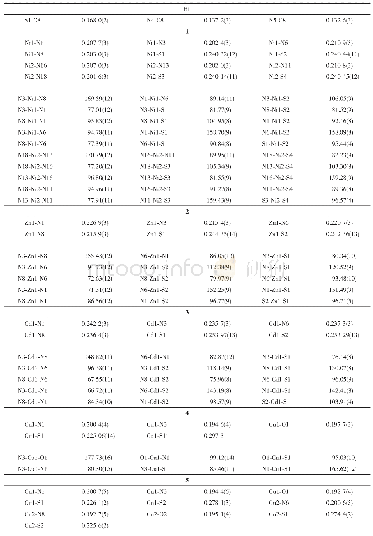
《Table 1.Measured Insertion Loss and Cross-talk at1550 nm for the Seven-core Fiber》
 提示:宽带有限、当前游客访问压缩模式
本系列图表出处文件名:随高清版一同展现
《50 GHz optical true time delay beamforming in hybrid optical/mm-wave access networks with multi-core optical fiber distribution》
The experimental setup is shown in Fig.3.The first block represents the CO,where three functionalities are implemented:wireless carrier selection,data modulation,and beamforming network.The optical carrier suppression(OCS)technique is used to generate two correlated optical lines,reducing the phase noise[1].A Mach–Zehnder modulator(MZM),which has been biased at the Vπpoint,is fed by a free-running external cavity laser atλ?1550 nm and an optical power of 13.0 d Bm(EMCORE TTX1994).The carrier frequency can be selected at this point by driving the radio frequency port by a sinusoidal tone with a frequency of fRF∕2.In this case,a vector signal enerator(VSG)provides a signal of 25 GHz and a power of5.4 d Bm.As a consequence,two spectral lines spaced at50 GHz(fRF)are generated at the optical output.Afterwards,the signal is boosted by an erbium-doped fiber amplifier(EDFA)before the following step.A second MZM is used to modulate with a 5 Gb/s(215-1)-bit-long pseudorandom bit sequence(PRBS15)non-return-to-zero(NRZ)signal provided by an arbitrary waveform generator(AWG)and a driving amplifier of 17 d B.In the last stage,the optical signal is powered up(12.7 d Bm)and split into the two branches that will feed the antenna array.The relative delay between them is manually controlled by two reconfigurable optical time delay lines(OTDL)with 0.033 ps resolution.They are both used to compensate length mismatches between the two paths and provide the desired delay configuration[Fig.3(a)].For experimental demonstration,a 1×2 beamformer network is implemented.However,the results can be generalized for a larger number of antenna elements.The OTDL outputs are launched into two different cores of a 2 km MCF,representing the optical link between the CO and RAU.The MCF used in this experiment is a seven-core fiber manufactured by OFS Labs[17].The cores are arranged in a regular hexagonal array by a central core with a core pitch of 38μm between all of them.The fiber is connected to two fan-in/fan-out modules by fusion splicing before being implemented in the system.The measured insertion loss and cross-talk are shown in Table 1.Cores 0 and 4 are chosen for this experiment because they have lower insertion loss.In a real scenario,the number of array elements would be limited by the number of cores.However,MCFs with many cores have already been developed(several tens).Moreover,different MCFs can be used to provide the delay configuration to different subsections of a larger array.Afterwards,the RAU A in Fig.1,working as a transmitter,is emulated.The radio frequency signals are generated on two 70 GHz bandwidth photodiodes(Finisar XPDV3120)acting as heterodyne mixers,keeping the relative delay from the optical domain[Fig.3(b)].The optical power before both photodiodes is fixed to 2.2 d Bm by two variable attenuators.This is the maximum power achieved with the described optical distribution network,which assures the operation below the saturation point of the photodiodes(3 d Bm).It can be seen in the optical spectrum in Fig.3 that the optical carrier is not completely suppressed,resulting in additional undesirable signals after photonic up-conversion.However,these photomixing products will be laid far enough from the frequency band of interest to be filtered out by the mm-wave components.Finally,a 70 GHz scope(Tektronik DPO70000SX Series)is used to capture the output signals for off-line processing[Fig.3(c)].
| 图表编号 | XD0022539400 严禁用于非法目的 |
|---|---|
| 绘制时间 | 2018.04.10 |
| 作者 | álvaro Morales、Idelfonso Tafur Monroy、Fredrik Nordwall、Tommi Srensen |
| 绘制单位 | Department of Electrical Engineering, Electro-Optical Communications, Eindhoven University of Technology、Department of Electrical Engineering, Electro-Optical Communications, Eindhoven University of Technology、Tektronix AB、GoMeasure ApS |
| 更多格式 | 高清、无水印(增值服务) |


