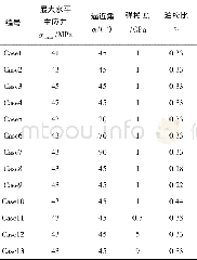
《Table 4 Boundary conditions for flow inlet and outlet》
In the present study,AA4045 is selected as a clad-layer because of its excellent brazing performance,and AA3003as a core-layer due to its well corrosion resistance.The chemical composition of the two aluminum alloys is listed in Table 1.The schematic diagram of experiment installation mainly consists of pouring systems,molds,cooling systems and starting head.Initially,the starting head was located in the mold.The core melt was poured into the inner-mold,forming a solid shell(called supporting layer)immediately.Then,the starting head was steadily withdrawn,and the clad melt was fed into the outer-mold at the same time.Through optimizing the casting parameters,the cladding billet,which is in size ofΦ140 mm/Φ110mm×1600 mm with perfect surface quality,was prepared.
| 图表编号 | XD0011283300 严禁用于非法目的 |
|---|---|
| 绘制时间 | 2018.11.01 |
| 作者 | 郭菁、韩星、藤莹雪、王洪斌、张海涛、农登 |
| 绘制单位 | 辽宁科技大学、辽宁忠旺集团有限公司、辽宁科技大学、辽宁科技大学、东北大学材料电磁过程研究教育部重点实验室、广东省材料与加工研究所 |
| 更多格式 | 高清、无水印(增值服务) |
 提示:宽带有限、当前游客访问压缩模式


