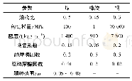
《表2 TFSS结构参数:兆瓦级回旋管单级降压收集极横向磁扫描系统的仿真(英文)》
 提示:宽带有限、当前游客访问压缩模式
本系列图表出处文件名:随高清版一同展现
《兆瓦级回旋管单级降压收集极横向磁扫描系统的仿真(英文)》
The table 3 gives a comparison between this schemes and other existing schemes from several aspects including operating frequency,collector dissipated power,adopted schemes and peak power density[13-14].The schemes 1 operates in lower values both in operating frequency and collector dissipated power.The peak power density is 130 W/cm2with TFSS only.The schemes 2employs VFSS with peak power density above 400W/cm2.Furthermore,the power supply for VFSS is much more complex and expensive than TFSS’s.This schemes adopt the same techniques with the schemes 3.Nevertheless,the collector dissipated power and peak power density are nearly twice and quarter respectively compared to schemes 3.The lower power density guarantees higher operating safety margin as well as enhances power capacity of collector to a large extent.At the same time,it also offers the possibility of higher RF power output for single gyrotron at 170 GHz.
| 图表编号 | XD0089654600 严禁用于非法目的 |
|---|---|
| 绘制时间 | 2019.08.01 |
| 作者 | 王恺、薛谦忠、张珊、赵鼎、张连正 |
| 绘制单位 | 中国科学院电子学研究所高功率微波源与技术重点实验室、中国科学院大学、中国科学院电子学研究所高功率微波源与技术重点实验室、中国科学院大学、中国科学院电子学研究所高功率微波源与技术重点实验室、中国科学院大学、中国科学院电子学研究所高功率微波源与技术重点实验室、中国科学院电子学研究所高功率微波源与技术重点实验室 |
| 更多格式 | 高清、无水印(增值服务) |


