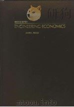
《RADIO ENGINEERING SECOND EDITION》
| 作者 | E.K. SANDEMAN 编者 |
|---|---|
| 出版 | 未查询到或未知 |
| 参考页数 | |
| 出版时间 | 没有确切时间的资料 目录预览 |
| ISBN号 | 无 — 求助条款 |
| PDF编号 | 820351048(仅供预览,未存储实际文件) |
| 求助格式 | 扫描PDF(若分多册发行,每次仅能受理1册) |
ⅠHow Broadcasting is Done8
1.Requirements to be met in a Broadcast Transmission8
2.Transmission from Studio to Aerial8
3.Reasons for Use of High-Frequency Currents in Aerial10
4.Modulation10
5.Production of Sidebands by Modulation12
6.Radiation13
7.Relation between Frequency and Wavelength14
8.Frequency Nomenclature and Tolerances15
8.1.Atlantic City Frequency Tolerances15
9.Allocation of Wavelength and Frequency Bands for Broadcasting15
10.B.B.C.Call Signs,Frequencies and Wavelengths used in Short-wave Services16
11.Chain of Apparatus involved in a Broadcast Transmission19
12.Limiting Amplifier or Limiter22
ⅡElectrical Effects and Units24
1.The Magnetic Field25
2.Electrons,Dielectrics(Insulators),and Conductors26
2.1.Convention for Direction of Current27
3.Electromotive Force=e.m.f.27
4.The Electric Field28
5.Potential Difference28
6.Field Strength=Strength of Electric Field29
7.Definition of the Volt29
8.Current and Magnetic Effect of a Current29
9.Definition of the Ampere,the Practical Unit of Current30
10.Electrical Quantity:Definition of the Coulomb,the Practical Unit of Electrical Quantity31
11.Linkage:E.M.F.induced by Change of Linkage31
12.Resistance:Definition of the Ohm,the Practical Unit of Resistance31
13.Wire Resistance32
13.1.Skin Effect36
13.2.The R.M.A.Colour Code43
14.Definition of the Watt,the Unit of Electrical Power44
15.Mechanical Equivalent of the W45
16.Thermal Equivalent of the W45
17.Inductance:Definition of the Henry,the Unit of Inductance45
17.1.Inductance of Air-Core Coils46
17.2.Best Coil Form49
17.3.The Coil Figure of Merit:Q49
17.4.Methods of Reducing the Effective Resistance of Coils50
17.5.Self-Capacity of Coils50
17.6.Miscellaneous Inductance Formulae51
18.Magneto-motive Force=m.m.f.57
19.Reluctance of a Magnetic Circuit57
20.Permeability58
21.Capacity(Capacitance)58
22.Definition of the Practical Units of Capacity:the Farad,the Microfarad and the Micro-Microfarad59
22.1.Capacity Formulae59
23.Dielectric Constant60
23.1.Dielectric Constants61
23.2.Characteristics of Shell KB30 Transformer Oil61
24.Condensers61
24.1.Electrolytic Condensers62
25.Interaction between Magnetic Field and Current64
26.Lenz's Law and its Inverse65
27.Thermo-electric Effect65
28.Contact Potentials65
29."Dry"and"Wet"Contacts65
30.Conversion Tables between Units66
31.Voltage Breakdown in Air76
31.1.Use of Spark Gaps as Voltage Limiters78
32.Other Physical Effects78
33.Mass and Weight79
34.Density and Specific Gravity79
35.Relations between Different Kinds of Energy80
36.Current-carrying Capacity of Conductors82
99.Numerical Examples84
ⅢThe Sine Wave and Vectors89
1.Trigonometrical Definitions89
2.Form of a Sine Wave92
3.Representation of Sine Waves by Vectors95
3.1.Addition of Vectors97
3.2.Derivation of Formulae for the Addition of Sine Waves and Vectors98
4.The Complex Plane100
5.Representation of the Angle of a Vector by ejθ104
6.Negative Vectors and Negative Angles105
7.Cosine Waves106
8.Solution of Triangles106
99.Numerical Examples107
ⅣRelations between Steady Voltages and Direct Currents110
1.Resistance and Conductivity110
2.Internal Electromotive Force in Generators110
3.Resistances in Series111
4.Resistances in Parallel112
5.Back Electromotive Force113
6.Power in Direct-Current Circuits113
6.1.Energy Stored in a Condenser114
6.2.Energy Stored in an Inductance114
7.Time Constants115
7.1.Resistance Capacity Circuits115
7.2.Resistance Inductance Circuits116
99.Numerical Examples118
ⅤRelations between Alternating Voltages and Currents120
1.Relation between Voltage across a Resistance,and Current120
2.Relation between Voltage across an Inductance,and Current120
3.Relation between Voltage across a Capacity,and Current122
4.Impedance and Complex Quantities123
5.Addition and Subtraction of Complex Quantities127
6.Multiplication of Complex Quantities128
7.Division of Complex Quantities128
8.Impedances in Series129
9.Condensers in Series129
10.Impedances in Parallel130
11.Admittance133
12.Vector and Scalar Notation and Mixed Notation133
13.The Principle of Superposition135
14.Reciprocity Theorem136
15.Thévenin's Theorem136
16.Parallel Representation of Impedances137
17.Reactance Chart140
18.Kirchhoff's Laws142
19.Impedance Potentiometers145
99.Numerical Examples147
ⅥSelective Circuits:Resonance and Tuning154
1.Series Resonance155
2.Parallel Resonance157
2.1.Condition at Parallel Resonance158
2.11.Relation between fr and fo160
2.2.Conditions for Maximum Impedance of a Parallel Resonant Circuit160
2.3.Natural Frequency161
2.4.Practical Application of Parallel Resonant Circuit161
2.5.Selectivity and Response162
2.6.Choice of Values of Elements in Tuned Circuits164
3.Rejector and Acceptor Circuits165
4.Other Types of Selective Circuit166
5.Decay Factor,Decay Index,Decrement,Q and Natural Frequency of a Circuit166
5.1.Definitions167
5.2.Measurement of Q,Decrement,Decay Factor and Decay Index of a Coil167
99.Numerical Examples172
ⅦPower in Alternating Current Circuits177
1.Power delivered to a Resistance by a Sinusoidal Alternating Current177
2.R.M.S.Sum of a Number of Alternating Currents or Voltages177
3.Power in Circuits containing both Reactance and Resistance178
4.Power Factor179
5.Power Ratios:The Decibel179
6.Level and Volume182
6.1.Level of Tone182
6.2.The Nature of Programme and Noise183
6.3.Volume of Programme and Noise184
6.4.Applications186
7.Levels in Speech and Music Circuits187
8.Level of Line-Up Tone and Use of Line-Up Tone187
9.Impedance Matching188
10.Reflection Loss190
10.1.Transition Loss191
11.Use of Impedance Transforming Circuits to avoid Reflection Loss192
12.Insertion Loss and Gain195
13.Coupled Circuits and Coupling Factor196
13.1.Leakage Flux196
13.2.Coupling Factor197
13.3.Mutual Inductance198
13.4.Leakage Inductance198
13.5.Impedance looking into Primary of Coupled Circuit198
13.6.Mutual Impedance199
13.7.Adjustment of Coupling199
14.Design of Impedance Matching or Coupling Circuits201
14.1.kVA to Kilowatts Ratio201
14.2.Current per Kilowatt through Inductances202
14.3.Design of Coupling Circuits in which the kVA/kW Ratio does not have to be considered204
14.31.Broad-Band Amplifiers211
14.32.Tuned Amplifiers(Narrow-Band Amplifiers)213
14.4.Method of Adjusting and Tuning Coupled Circuits214
14.5.Design of Coupling Circuits in which the kVA/kW Ratio has to be taken into Account215
14.6.Design of Coupling Circuits without the use of Charts217
15.Effective Inductance of two Inductances L1 and L2 with Mutual Coupling M between them218
16.Measurement of Coupling Factor k of two Inductances220
17.Attenuators220
17.1.Attenuators in which Z1 and Z2 are unequal:Dissymmetrical T and π Networks224
99.Numerical Examples225
ⅧHarmonic Analysis and Dietortion230
1.Periodic Waves230
1.1.Spectra of Amplitude Modulated Waves239
2.Spectrum of Speech and Music243
3.Distortion248
3.1.Response Distortion:Response Characteristics248
3.11.Permissible Deviation of Response Characteristics in Audio-Frequency Circuits250
3.2.Phase Distortion in Audio-Frequency Circuits252
3.3.Non-Linear Distortion258
4.Effects of Distortion in Radio-Frequency Circuits259
4.1.Measurement of Distortion in Radio-Frequency Circuits260
4.2.Effect of Attenuation and Phase Shift of Sidebands260
ⅨThermionic Valves264
1.The Diode264
2.The Triode266
3.Anode Impedance=Ro267
4.Load Line269
4.1.Use of the Load Line271
4.2.Grid Bias and Cut-Off273
5.Voltage Amplification273
6.Voltage Amplification Factor of Valve=μ275
7.Mutual Conductance of Valve=gm276
7.1.Relation between gm,μ and Ro276
8.Power Amplification277
9.Non-Linearity277
10.Capacities in a Triode278
11.The Screen-Grid Valve or Tetrode279
11.1.Secondary Emission279
12.The Pentode280
13.Mixers282
13.1.Hexode282
13.2.Heptode283
13.3.Octode283
14.Variable μ Valves283
15.Composite Valves284
16.Short-Wave Valves284
17.Anode Dissipation285
17.1.Air-Cooled Anodes285
17.2.Water-Cooled Anodes285
17.3.Cooling of Seals286
18.Operation and Maintenance of Thermionic Valves286
18.1.Procedure for Applying Supplies to a Valve286
18.2.Marked Volts(Filament Volts)287
18.3.New Valves(Introduction into service of)289
18.4.Gas Test289
18.41.Pirani Test290
18.5.Service Test on Spare Valves290
18.6.Emission Tests290
18.61.Total Emission Test290
18.62.Suppressed Emission Test290
18.63.Emission Tests on Medium-Size Valves and Small Valves291
18.7.Valve Cooling Water291
19.Total Emission,Peak Emission,Peak Anode Current,and Cathode Emission291
20.Grid Input Impedance of Valves293
21.Transmitting Valves294
ⅩAmplifiers295
1.Class A Amplifiers295
1.1.Phase Relation between Grid Volts and Anode Volts298
2.Resistance-Coupled Amplifier299
3.Choke-Coupled Amplifier300
4.Load Line for Resistance-Coupled Amplifier300
5.Load Line for Choke-Coupled Amplifier301
6.Transformer-Coupled Amplifier302
7.Automatic Grid Bias304
8.Push-Pull Connection of Valves305
9.Class B Amplifiers308
10.Design of Push-Pull Output Transformers for Class A and Class B Amplifiers309
11.Power Output and Efficiency of Class B Amplifiers310
11.1.Comparison of Power Output of Class A and Class B Amplifiers:Adjustment of Load Line for Maximum Output312
12.Variation of Power Consumption of Anode Circuit of Amplifier as Grid Drive Varies318
13.Variation of Anode Dissipation as Grid Drive Varies319
14.Theoretical Optimum Value of Anode Load Impedance319
15.Tuned Amplifiers321
16.Definitions of A,B,and C Tuned Amplifiers323
17.Circuit Arrangement of Tuned Amplifiers324
18.Make-up Current326
19.Neutralization of Anode-Grid Capacity of Valves326
19.1.Circuits which Provide Stability and Freedom from Feedback327
19.11.The Split Anode Neut Circuit327
19.12.Push-Pull Neut Circuit329
19.13.Inductance-Capacity Potentiometer Neut Circuit331
19.2.The Split-Grid Neut Circuit332
19.3.Neut Circuit in High-Power Tetrodes334
20.Adjustment of Neut Condensers335
20.1.Method Ⅰ.Direct Adjustment of Loss335
20.2.Method Ⅱ.Grid Current Method336
20.3.Method Ⅲ.Anode-Current Grid-Current Method337
20.4.Method Ⅳ.Anode Current Method338
20.5.Method of Neuting to Use338
20.6.Neuting of Short-Wave Amplifiers340
21.Design of Class A Tuned Amplifiers340
22.Class B and C Tuned Amplifiers340
22.1.Definition of Angle of Current Flow342
22.2.Relation between Angle of Current Flow and Anode Current Ratios:Peak Fundamental to Peak,Peak Fundamental to Mean,and Mean to Peak Ratio342
22.3.Relation between Load Line in Class C Amplifier and Impedance Facing Anode345
23.Power Output of a Class C Tuned Amplifier346
23.1.Power Output of a Class B Amplifier347
24.Anode Efficiency of a Class C Tuned Amplifier347
24.1.Anode Efficiency of a Class B Amplifier(See also X:30)347
24.2.Anode Efficiency of a Class B Tuned Amplifier Transmitting a Modulated Wave347
25.The Angle of Current Flow348
25.1.Determination of θ,the Angle of Current Flow348
25.2.Effect of Changing the Angle of Current Flow,θ351
25.21.Comparison of Performance of Class B and Class C Tuned Amplifiers(Relation between Angle of Current Flow,Grid Peak Volts,Effective Grid Peak Volts,Working Bias and Cut-off Bias)353
25.22.Detailed Examination of the Effect of Changing the Angle of Current Flow in a Class C Amplifier357
25.3.Choice of Angle of Current Flow359
25.4.Determination of Grid Bias and Grid Drive to Produce a Required Angle of Current Flow360
26.Practical Design of a Class C Amplifier361
26.1.Grid Loading of Linear Class B Amplifiers364
26.2.Choice of Valve for use in Class C Amplifiers365
26.3.Determination of Working Conditions of a Class C Amplifier which is not driven into Anode Limitation368
26.31.Determination of Anode Load Impedance369
27.Anode Limitation370
27.1.Asymptote377
28.Variation of Anode Current as Anode Circuit is Tuned377
29.Variation of Grid Current as Anode Circuit is Tuned378
30.Working Conditions of Class B Tuned Amplifier taking into account No-Drive Standing Feed378
31.Examination of a Practical Tuned Amplifier381
32.Design of Output Coupling Circuit for a Push-Pull Class B or C Tuned Amplifier384
33.Practical Measurement of Valve Anode Efficiency385
33.1.Measurement of Valve Anode Eficiency by Temperature Rise of Anode Cooling Water386
34.Anode Peak Volts and Anode Peak Current in a Modulated Amplifier or other Amplifier driven into Anode Limitation388
35.Inverted Amplifier389
35.1.Necessity for Modulating the Drive Stage392
35.2.Summary393
35.3.Circuit of Practical Inverted Amplifier and Driver393
35.4.Design of Inverted Amplifier and Driver Stage394
35.5.Relations in a Class A Inverted Amplifier397
35.6.Relations in a Class C Inverted Amplifier398
35.61.Power Output from an Inverted Amplifier399
35.62.Power Amplification of an Inverted Amplifier399
35.63.Percentage Modulation Realizable with an Inverted Amplifier400
35.7.Operation and Adjustment of Inverted Amplifiers400
36.Short-Wave Amplifiers401
37.Valve Anode Efficiency,Valve Anode Circuit Efficiency and Output Efficiency of an Amplifying Stage401
38.Grid Dissipation in a Class C Amplifier403
39.D.C.Amplifiers404
99.Examples407
ⅪOscillators414
1.Early Views on Oscillators414
1.1.Standard Oscillator Circuits418
1.2.Frequency Stabilization of Oscillators419
2.Present Views on Oscillators423
2.1.Series Resonance Osciliator423
3.Design and Performance of a Practical Oscillator427
4.Crystal Oscillators430
4.1.The AT Cut Plate433
4.2.Frequency Stability of Crystal Oscillators using AT Cut Plates435
4.3.Crystal Oscillator Circuits435
4.31.Series Resonance Type435
4.32.The Meacham Crystal Bridge Oscillator Circuit436
4.33.Miller Circuit Crystal Oscillator437
4.4.Crystal Ovens439
5.Dynatron Oscillators441
6.The Two Types of Negative Resistance442
7.Resonant Line Oscillators442
8.Electron-Coupled Oscillator445
9.Beat Oscillators446
9.1.Intermodulation of Two Frequencies in a Square Law Modulator446
9.2.Frequency Stability of Beat Oscillators448
10.Resistance-Capacity Oscillator449
11.Freak Oscillations451
12.Parasitic Oscillations452
12.1.Detection of Parasitic Oscillations452
12.2.Causes of Parasitic Oscillation—particularly affecting Audio-Frequency Amplifiers453
12.3.Causes of Parasitic Oscillations—particularly affecting Radio-Frequency Amplifiers456
12.4.Location of Parasitic Oscillations461
12.41.Inter-stage Oscillations463
12.42.Oscillations involving Input and output Lines463
12.43.Oscillations Internal to Stage464
12.44.Oscillations in R.F.Amplifiers464
13.Stability Tests on Transmitters465
ⅫDrive Equipment467
1.Definition of Drive Equipment467
2.Cairo Requirements on Frequency Stability of Transmitters467
3.Synchronized Operation of Transmitters on the same Wavelength467
4.The Beat Indicator469
4.1.Cathode Ray Tube Indicator471
5.Methods of Frequency Checking and Adjustment in Synchronized Groups471
5.1.Frequency Checking by Radio471
5.2.Frequency Checking By Line472
6.Frequency Dividers473
6.1.Locked Oscillators473
6.2.Multivibrators473
6.21.Single-Circuit Divider477
6.211.Method of Operation478
6.22.Locking of Multivibrators480
6.221.Locking Condition for Division by an Odd Number481
6.222.Locking Condition for Division by an Even Number482
6.223.Adjustment of Relative Lengths of the Two Half-Periods of a Multivibrator483
6.3.Modulator Dividers484
7.Frequency Multipliers489
7.1.Harmonic-Generator Multiplier490
7.2.Harmonic Generators for Multiplying by Odd Numbers491
7.3.Harmonic Generators for Multiplying by Even Numbers491
7.4.Limitation on Multiplication Factor493
8.Vernier Scales496
ⅩⅢModulators and Modulation498
1.Different Types of Modulation498
2.Heising or Choke Modulation501
3.Class B Modulation503
3.1.Temporary Conversion of Class B Modulator to Class A Operation505
3.2.Series Modulation505
3.3.Design of a Series Modulator508
4.Principle of a Modulated Amplifier509
4.1.Upward and Downward Modulation in Modulated Amplifiers516
4.2.Initial Adjustment of a Modulated Amplifier517
4.3.Simple Procedure for adjusting a Modulated Amplifier522
4.4.Power Handling Capacity525
5.Diode Modulator526
6.Class C Grid Modulator528
7.Anode Bend Modulator532
8.Suppressor Grid Class C Modulator535
8.1.Anode Modulation of Pentode(Suppressor Grid Modulator)538
9.Conversion to 100% Modulation538
10.Push-Pull or Balanced Modulators539
10.1.Double Balanced Modulator541
10.2.Use of Tetrodes in Modulated Amplifier544
11.Spectrum of Modulated Wave544
11.1.Amplitude-Modulated Wave544
11.2.Phase-Modulated Wave548
11.3.Frequency-Modulated Wave549
11.4.Modulation by a Band of Frequencies550
11.5.Numerical Determination of Spectra of Frequency-Modulated and Phase-Modulated Waves552
11.6.Frequency Range occupied by a Frequency-Modulated or a Phase-Modulated Wave557
11.7.Reduction of Noise Level at the Receiver in a Frequency-Modulation System558
11.71.Behaviour of the Limiter559
11.72.Demonstration that the Effective Noise Level in the Receiver is inversely proportional to the Amplitude of Carrier Frequency Swing559
11.73.Comparison of Speech-to-Noise Ratios in Amplitude-Modulated and Frequency-Modulated Systems561
11.8.False Phase Modulation563
12.Heising Modulation Formulae564
ⅩⅣTransmitter Types568
1.Trend of Development568
2.Low-Power Modulation568
3.Series Modulation569
4.Class B Modulation569
5.The Chireix System569
6.The Doherty System572
6.1.The Improved Doherty System576
6.11.Design of a Doherty Amplifier576
6.2.Grid-Modulated Doherty Amplifier578
6.21.Design of Grid-Modulated Doherty Amplifier579
6.22.Example of a Practical Circuit586
6.23.Representation of Voltages and Currents in a Grid-Modulated Doherty Amplifier591
7.The Fortescue System594
8.The Floating Carrier System595
9.Efficiencies of Output Stages of Different Systems597
9.1.Class A High-Power Modulation(includes Heising and Series Modulation)597
9.2.Class B High-Power Modulation598
9.3.Low-Power Modulation599
9.4.The Chireix System599
9.5.The Doherty System600
9.51.The Improved Doherty System601
9.6.The Fortescue System602
10.Comparison of Different Systems603
11.Observed Overall Efficiency of Transmitters605
12.H.T.Smoothing Circuits607
12.1.Class B System608
ⅩⅤOperation and Maintenance of Transmitters613
1.Starting UP a Transmitter613
1.1.Putting a New Valve into Service614
2.Shutting Down a Transmitter614
3.Shutting Down in Extreme Emergency615
4.Line-up of Transmitter for Modulation615
4.1.Old-Type Programme Meter615
4.2.Peak Programme Meter616
5.Running Adjustments616
6.Installation of Spare Valves616
7.Changing Wave617
8.Reducing Power Output of a Transmitter619
8.1.Reducing the Number of Valves620
8.2.Reducing Coupling621
8.3.Reduction of H.T.622
9.Operation of Transmitters in Parallel on the Same Wavelength622
10.Prevention and Clearance of Faults624
10.1.Maintenance Routines on Valves624
10.2.Maintenance Routines on Transmitters624
10.3.Clearing Faults625
10.31.Fault Analysis626
11.Flashover626
11.1.Procedure when a Flashover Occurs626
11.2.Cause of Flashover626
ⅩⅥFeeders,Aerial-Coupling Cirouits and Aerials628
1.The Behaviour of Feeders629
1.1.Characteristic Impedance=Zo632
1.2.Loop Inductance,Capacity per Unit Length and Characteristic Impedances of Three Types of Feeder632
1.3.Propagation Constant,Attenuation Constant and Phase Shift Constant.Relations between Voltages and Currents in Properly Terminated Feeder and Sending-End Voltages and Currents635
1.4.Relation between Wavelength λ and Phase Constant α638
1.5.Phase Velocity of a Progressive Wave.Relations between Phase Velocity,Wavelength and Frequency638
1.6.Attenuation of Feeders639
1.7.Standing Waves640
1.71.Instantaneous Voltages in an Open-Circuited Line640
1.72.Instantaneous Currents in an Open-Circuited Line643
1.73.Instantaneous Voltages and Currents in a Short-Circuited Line643
1.74.Derivation of Formulae for Voltages and Currents in Open-Circuited Line and Sending-End Impedance644
1.75.Voltages and Currents in Short-Circuited and Sending-End Impedance645
1.8.Line terminted in an Impedance not equal to its Characteristic Impedance646
1.81.Determination of Ratio between Incident and Reflected Currents and Voltages646
1.82.Sending-End Impedance of Line of Characteristic Impedance Z0,terminated in an Impedance Z647
1.9.Determination of Wavelength in a Feeder or Transmission Line649
1.10.Nodes and Antinodes in a line terminated in a Mismatched Load-Taking Power649
2.Circle Diagrams650
2.1.Method of Entering Parallel Represented Impedances652
3.Impedance Matching in Feeders656
3.1.Magnitude of Standing Waves656
3.11.Standing Wave Ratio657
3.12.Use of Circle Diagram to determine the Magnitude of the Standing Wave Ratio in a Feeder658
3.2.Determination of Terminal Impedance from the Currents at Nodes and Antinodes659
3.3.Impedance Matching in Short-Wave Feeders.Use of Tails for Impedance Matching659
3.4.Impedance Matching by Use of Inserted Length of Feeder of Different Inpedance from the Main Feeder662
4.The Quarter-Wave Line666
5.Feeders as Filters668
5.1.The Tapped Quarter-Wave Line670
6.Conductor Sizes and Power-Carrying Capacity of Feeders671
7.Short-Wave Transmitting Aerials672
7.1.Arrangement and Method of Designation of Short-Wave Arrays675
7.11.Performance of Arrays676
7.111.Power-Density Diagrams676
7.112.Calibration of Power-Density Diagrams687
7.2.Slewing of Arrays688
7.3.Reflectors688
7.4.The Impedance Presented by a Half-Wave Dipole690
7.41.Centre-Fed Dipole690
7.42.Shunt-Fed Dipole691
7.43.End-Fed Dipole691
7.5.Impedance of an Array692
7.6.Size of Conductor used in Dipole Arrays692
7.7.Kraus Aerial693
7.8.Lengths of Half-Wave Dipoles693
8.Impedance Matching in Medium and Long-Wave Feeders695
8.1.Essential Points to be observed in Adjustment of Aerial Circuits695
8.2.Aerial-Coupling Unit696
8.3.Equivalence of Series and Parallel Impedances697
8.4.L Networks for Use as Impedance Transforming Sections698
8.5.Method of Setting Up Aerial Coupling Circuits700
8.51.Choice of Form of Circuit on Secondary Side of the Coupling Unit702
8.6.Matching of Low Impedances704
9.Insertion of Rejector Circuits for the Prevention of"Throw-in"705
10.Operation of Two Transmitters on Different Wavelengths into a Single Aerial709
11.Losses in Aerial Tuning Huts709
12.Impedance Matching in Long-Wave Aerial Circuits710
12.1.Principles of Design in Long-Wave Aerial Circuits of B.B.C.Transmitter at Droitwich715
12.11.Simulation of Reactance Curve by Series Resonant Circuit716
12.12.Neutralization of Aerial Reactance717
12.13.Power Factor Correction at Two Sideband Frequencies718
12.14.Calculation of Circuit Impedances720
12.15.Frequency Response726
12.16.Analysis of Circuit used at Droitwich and Method of Design of Component Networks to Build up Overall Required Phase Shift727
13.Relations between Inductance and Capacity per Metre,Characteristic Impedance and Phase Velocity731
13.1.Inductance of Straight Vertical Wire732
13.2.Value of Condenser required to Neutralize Reactance of Grid Lead733
13.3.Elimination of Phase Shift in Grid Lead735
13.4.Neutralization of Reactance of Earth Lead737
14.Stress Diagrams in Aerial Arrays738
14.1.Vector Conventions739
14.2.Force and Space Diagrams740
14.3.Bow's Notation741
14.4.Catenary741
14.5.Triatic with Single Load744
14.6.Multi-loaded Triatic747
14.7.Curtain Array750
14.8.Windage and Ice753
14.9.Factors of Safety754
Index757
《RADIO ENGINEERING SECOND EDITION》由于是年代较久的资料都绝版了,几乎不可能购买到实物。如果大家为了学习确实需要,可向博主求助其电子版PDF文件。对合法合规的求助,我会当即受理并将下载地址发送给你。
高度相关资料
-

- THERMOPLASTICS:MATERIALS ENGINEERING SECOND EDITION
- 1989 ELSEVIER
-

- Marketing Engineering(Second Edition)
- Arvind Rangaswamy 著
-
- THEORETICAL FOUNDATIONS OF COMPUTER GRAPHICS AND CAD
- 1988 SPRING VERLAG
-

- CONTROL ENGINEERING SECOND EDITION
- 1998 LONGMAN
-

- ENGINEERING ECONOMICS SECOND EDITION
- 1982 COPYRIGHT
-

- AIRPORT ENGINEERING SECOND EDITION
- 1984 JOHN WILEY
-
- ENGINEERING AND ENGINEERING DESIGN SECOND EDITION
- 1969 JOHN WILEY & SONS
-

- Environmental engineering second edition
- 1988 Butterworths
-

- SOFTWARE ENGINEERING SECOND EDITION
- 1993 IRWIN
-

- THE RADIO STATION SECOND EDITION
- 1989 FOCAL PRESS
-

- ENGINEERING GRAPHICS SECOND EDITION
- 1988 Prentice Hall
提示:百度云已更名为百度网盘(百度盘),天翼云盘、微盘下载地址……暂未提供。➥ PDF文字可复制化或转WORD

