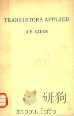
《TRANSISTORS APPLIED》
| 作者 | H.E.KADEN 编者 |
|---|---|
| 出版 | PHILIPS TECHNICAL LIBRARY |
| 参考页数 | 194 |
| 出版时间 | 1965(求助前请核对) 目录预览 |
| ISBN号 | 无 — 求助条款 |
| PDF编号 | 813251178(仅供预览,未存储实际文件) |
| 求助格式 | 扫描PDF(若分多册发行,每次仅能受理1册) |
CHAPTER 1INTRODUCTION1
1.1.The transistor versus the tube1
1.2.The fundamental circuit of the transistor and the electron tube1
1.3.Why does the transistor amplify?1
1.4.Why does the electron tube amplify?2
1.5.How strongly does an electron tube amplify?3
1.6.How much does a transistor amplify?7
1.7.What simple circuit illustrates amplification in the elec-tron tube?13
1.8.What simple circuit illustrates amplification in the transistor?14
1.9.How is the working point set?15
1.10.What is the effect of feedback?16
1.11.What is the residual current?19
1.12.How does temperature affect the transistor?19
1.13.What is “stabilisation”?20
1.14.What peculiarities have the cathode follower and the common collector circuit?20
1.15.Are the earthed grid stage and the common base stage equal to each other?21
1.16.A word about current and voltage directions22
CHAPTER 2PHYSICAL PRINCIPLES OF THE TRANSISTOR24
2.1.The conduction mechanism in germanium24
2.1.1.Crystal structure24
2.1.2.Intrinsic conduction24
2.1.3.Extrinsic conduction25
2.2.The p-n boundary layer27
2.3.The p-n-combination as rectifier29
2.4.The junction transistor30
CHAPTER 3SYMBOLS,SIGNS,FUNDAMENTAL CIRCUIT32
CHAPTER 4THE FOUR QUADRANT CHARACTERISTIC FIELD34
CHAPTER 5TWO-POLE REPRESENTATION OF THE TRANSISTOR39
CHAPTER 6TRANSISTOR EQUIVALENT CIRCUIT46
6.1.Voltage equivalent circuit46
6.2.Current equivalent circuit46
CHAPTER 7FIXING THE OPERATING POINT48
7.1.Fixing with series resistance48
7.2.Adjustment with low resistance voltage divider49
CHAPTER 8APPARENT INTERNAL RESISTANCE WITH LOAD VARIATION52
CHAPTER 9TRANSISTORS WITH NEGATIVE FEEDBACK58
9.1.Series feedback59
9.1.1.Voltage control;influence of the control generator66
9.1.2.The apparent transistor characteristic values with series feedback70
9.2.Parallel feedback72
9.2.1.Current control;influence of the control generator77
9.2.2.The apparent characteristic values ofthe transistor with parallel feedback80
9.3.Stabilisation characteristic value83
9.4.Non-linear distortions85
9.4.1.The non-linear distortion factor85
9.4.2.Improving the non-linear distortion factor86
9.5.Working point stabilisation88
CHAPTER 10THE INFLUENCE OF TEMPERATURE ON THE TRANSISTOR92
10.1.Permissible transistor dissipation92
10.2.Temperature influence on the collector current94
10.2.1.Constant d.c.base and collector voltage96
10.2.2.Load resistance99
10.2.3.Temperature stabilisation by means of feedback101
10.2.4.Temperature compensation with thermistors102
10.2.5.Stabilisation by a base series resistance103
CHAPTER 11TRANSISTOR LEAKAGE CURRENTS104
11.1.Unstabilised circuit105
11.2.Leakage current influence with stabilised constant base current105
11.3.The leakage current influence with stabilisation of the emitter current107
11.4.Leakage current influence with stabilisation of the collector current110
CHAPTER 12DIRECT CURRENT AMPLIFICATION114
12.1.Emitter circuit114
12.2.Base circuit115
CHAPTER 13CHARACTERISTIC VALUES AND THEIR DE-PENDENCE UPON THE WORKING POINT116
13.1.The transistor as regulating device118
CHAPTER 14THE COMMON COLLECTOR CIRCUIT121
14.1.The equivalent characteristic values of the common collector stage127
CHAPTER 15THE COMMON BASE CIRCUIT130
15.1.The equivalent characteristic values of the common base stage134
CHAPTER 16HIGH FREQUENCY BEHAVIOUR OF THE TRANSISTOR136
16.1.Transistor capacitances136
16.1.1.Barrier layer capacitance Cr136
16.1.2.Diffusion capacitance Ci137
16.1.3.The output capacitance Co139
16.2.The high frequency equivalent circuit diagram139
16.3.Limiting frequencies141
16.3.1.The limiting frequency of short-circuit current amplification142
16.3.2.The upper limiting frequency of voltage ampli-fication in the common emitter circuit151
16.3.3.The upper limiting frequency of voltage ampli-fication in the common base circuit152
CHAPTER 17MULTISTAGE LF AMPLIFIERS158
17.1.RC amplifier158
17.1.1.Upper limiting frequency159
17.1.2.Lower limiting frequency160
17.1.3.The emitter capacitance CE162
17.2.Transformer coupling165
17.2.1.Current control166
17.2.2.Output matching166
CHAPTER 18RESONANCE AMPLIFIER168
18.1.Neutralisation171
18.2.Bandfilter coupling171
CHAPTER 19AMPLIFIER NOISE175
19.1.Resistance noise175
19.2.Transistor noise178
CHAPTER 20SUMMARY OF COMPARISONS BETWEEN THE TRANSISTOR AND ELECTRON TUBE183
20.1.Formula and circuit comparison184
Symbols190
Bibliography191
Index193
1965《TRANSISTORS APPLIED》由于是年代较久的资料都绝版了,几乎不可能购买到实物。如果大家为了学习确实需要,可向博主求助其电子版PDF文件(由H.E.KADEN 1965 PHILIPS TECHNICAL LIBRARY 出版的版本) 。对合法合规的求助,我会当即受理并将下载地址发送给你。
高度相关资料
-

- TRANSISTORS THEORY AND CIRCUITRY
- 1964 MCGRAW-HILL PUBLISHING COMPANY LIMITED
-
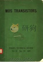
- MOS TRANSISTORS
- PHILIPS TECHNICAL REVIEW
-
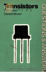
- Transistors
- 1969 Newnes Technical Books
-
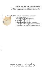
- THIN FILM TRANSISTORS
- 1969 WILEY & SONS INC
-
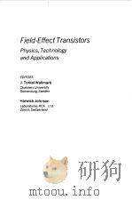
- FIELD EFFECT TRANSISTORS
- 1966 PRENTICE HALL INC
-
- TRANSISTORS FOR TECHNICAL COLLEGES
- 1965 LONDON ILIFFE BOOKS LTD.
-
- THE PHYSICAL THEORY OF TRANSISTORS
- 1961 MCGRAW-HILL BOOK COMPANY
提示:百度云已更名为百度网盘(百度盘),天翼云盘、微盘下载地址……暂未提供。➥ PDF文字可复制化或转WORD
