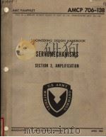
《ENGINEERING DESIGN HANDBOOK SERVOMECHANISMS SECTION 3 AMPLIFICATION》
| 作者 | 编者 |
|---|---|
| 出版 | 未查询到或未知 |
| 参考页数 | 199 |
| 出版时间 | 没有确切时间的资料 目录预览 |
| ISBN号 | 无 — 求助条款 |
| PDF编号 | 811829618(仅供预览,未存储实际文件) |
| 求助格式 | 扫描PDF(若分多册发行,每次仅能受理1册) |
CHAPTER 13AMPLIFIERS USED IN CONTROLLERS1
13-1ELECTRONIC AMPLIFIERS1
13-1.1 VACUUM TUBES1
13-1.2 Diodes1
13-1.3 Control of electron flow2
13-1.4 Diodes as rectifiers2
13-1.5 Triodes3
13-1.6 Plate characteristics3
13-1.7 Graphical analysis3
13-1.8 Linear approximations4
13-1.9 Region of operation4
13-1.10 Linear equivalent circuits4
13-1.11 Alternate linear equivalent circuit5
13-1.12 Quiescent operating point5
13-1.13 Phase shift5
13-1.14 Pentodes and Beam-Power Tubes5
13-1.15 Plate characteristics6
13-1.16 Linear equivalent circuits6
13-1.17 Graphical analysis6
13-1.18 Interelectrode Capacitance6
13-1.19 Tube Specifications7
13-1.20 LINEAR ANALYSIS OF SINGLE-STAGE VACUUM-TUBE VOLTAGE AMPLIFIERS7
13-1.21 Characteristics of Tubes Used7
13-1.22 Simple Amplifier7
13-1.23 Series Tube Triode Amplifier8
13-1.24 Cascode Amplifier8
13-1.25 Cathode Followers9
13-1.26 Simple Feedback Amplifier11
13-1.27 Differential Amplifiers12
13-1.28 Use of Pentodes13
13-1.29 POWER AMPLIFIERS13
13-1.30 Tubes Used in Power Amplifiers13
13-1.31 Push-Pull Power Amplifiers14
13-1.32 Analysis of push-pull power amplifiers15
13-1.33 Push-pull amplifier with a-c supply15
13-1.34 Efficiency15
13-1.35 CASCADING AMPLIFIER STAGES15
13-1.36 Direct-Coupled Amplifiers15
13-1.37 Problems encountered in direct-coupled amplifiers18
13-1.38 Drift-compensated direct-coupled amplifier19
13-1.39 Bridge circuits19
13-1.40 A-C Coupled Amplifiers21
13-1.41 Two-stage a-c coupled amplifier21
13-1.42 FEEDBACK AMPLIFIERS23
13-1.43 Advantages23
13-1.44 Disadvantages25
13-1.45 PROBLEMS ENCOUNTERED IN USE OF ELEC-TRONIC AMPLIFIERS AS SERVO COMPONENTS26
13-1.46 Reliability26
13-1.47 Construction27
13-1.48 Maintenance27
13-1.49 Quadrature Signals27
13-1.50 Complete Amplifier27
13-1.51 Details of a Typical Servo Amplifier28
13-1.52 THYRATRON AMPLIFIERS28
13-1.53 Description of Thyratron28
13-1.54 Thyratron Characteristics30
13-1.55 Thyratron Amplifier with Resistive Load30
13-1.56 Control of Load Voltage31
13-1.57 Thyratron-Amplifier Loads32
13-1.58 Resistive loads33
13-1.59 Inductive loads33
13-1.60 Battery,capacitive,and separately excited d-c motor loads34
13-1.61 Dynamic Performance35
13-1.62 Exception to time-constant rule35
13-1.63 D-C POWER SUPPLIES FOR ELECTRONIC AM-PLIFIERS35
13-1.64 Types of Rectifiers35
13-1.65 Power-Supply Circuits35
13-1.66 Design of D-C Power Supplies36
13-1.67 Typical electronic regulator37
13-2TRANSISTOR AMPLIFIERS38
13-2.1 BASIC PRINCIPLES38
13-2.2 Operating Characteristics of Temperature-Limited Vacuum Diode38
13-2.3 Transistor Operation39
13-2.4 Advantages and disadvantages of transistors39
13-2.5 High-frequency operation39
13-2.6 Medium-frequency operation39
13-2.7 High-power applications40
13-2.8 Switching applications40
13-2.9 Summary40
13-2.10 BASIC THEORY OF JUNCTION DIODES AND TRANSISTORS40
13-2.11 Electron Current40
13-2.12 Hole Current40
13-2.13 Material Types41
13-2.14 Junctions41
13-2.15 Junction Diodes41
13-2.16 Junction Transistors42
13-2.17 Special transistor types42
13-2.18 Characteristics of transistor materials42
13-2.19 ANALYSIS OF TRANSISTOR CHARACTERISTICS43
13-2.20 Transistor Model43
13-2.21 Piecewise linear model44
13-2.22 Incremental model44
13-2.23 Hybrid Parameters46
13-2.24 Frequency Dependence46
13-2.25 Temperature Sensitivity47
13-2.26 Nonuniformity47
13-2.27 Noise Factor50
13-2.28 Microphonics and Vibration Effects50
13-2.29 Maximum Collector Voltage50
13-2.30 Maximum Power Dissipation50
13-2.31 TRANSISTOR AMPLIFIER CIRCUITS50
13-2.32 Grounded-Emitter Amplifier50
13-2.33 Grounded-Base Amplifier50
13-2.34 Grounded-Collector Amplifier51
13-2.35 Phase-Inverter and Difference-Amplifier Circuits51
13-2.36 High Power Amplifiers51
13-2.37 Maximum power output52
13-2.38 Biasing52
13-2.39 Typical Two-Stage Transistor Amplifier54
13-2.40 Direct-Coupled Amplifiers54
13-2.41 State of the Art55
13-2.42 A-C POWER AMPLIFIER DESIGN55
13-3MAGNETIC AMPLIFIERS58
13-3.1 BASIC CONSIDERATIONS58
13-3.2 Functions of Magnetic Amplifiers in Servo Systems58
13-3.3 Features of Magnetic Amplifiers58
13-3.4 Application Problems of Magnetic Amplifiers58
13-3.5 Temperature Limitations58
13-3.6 Design Difficulties58
13-3.7 PRINCIPLES OF OPERATION59
13-3.8 Single-Core,Single-Rectifier Circuit59
13-3.9 Operating cycle of a single-core circuit59
13-3.10 Exciting and conducting periods60
13-3.11 Reset period60
13-3.12 Control limits60
13-3.13 Control characteristics61
13-3.14 Analysis limitations61
13-3.15 Analysis extension62
13-3.16 TYPICAL CIRCUITS62
13-3.17 Half-Cycle(Ramey)Circuit62
13-3.18 Single-Ended,Two-Core Circuits62
13-3.19 Operation of two-core circuits63
13-3.20 Reversible-Polarity and Reversible-Phase Circuits63
13-3.21 Example of reversible-phase amplifier63
13-3.22 ANALYTICAL REPRESENTATION OF MAGNETIC AMPLIFIERS64
13-3.23 Dynamic Performance64
13-3.24 Dynamic response65
13-3.25 Accuracy of prediction65
13-3.26 Analytical Representation65
13-3.27 Effectivecontrol-circuit resistance65
13-3.28 Limitations in analytical representation66
13-3.29 Conclusions66
13-3.30 PERFORMANCE OF MAGNETIC AMPLIFIERS66
13-3.31 Ranges of Input and Output Power66
13-3.32 Control Characteristics66
13-3.33 Figure of Merit66
13-3.34 Typical values of Figure of Merit68
13-3.35 Expression for Figure of Merit69
13-3.36 Largest factor70
13-3.37 Effects of dimensions70
13-3.38 Leakage effects70
13-3.39 Temperature effects70
13-3.40 CONSTRUCTION OF MAGNETIC AMPLIFIERS70
13-3.41 Methods of Core Construction70
13-3.42 Relative merits71
13-3.43 Core Materials71
13-3.44 Applications71
13-3.45 Rectifiers72
13-3.46 Characteristics of selenium rectifiers72
13-3.47 Characteristics of germanium rectifiers72
13-3.48 Characteristics of silicon rectifiers72
13-3.49 Factors governing choice of rectifier type72
13-3.50 SPECIFICATIONS AND DESIGN72
13-3.51 Specifications72
13-3.52 Approach to Design73
13-4ROTARY ELECTRIC AMPLIFIERS73
13-4.1 TYPES OF ROTARY ELECTRIC AMPLIFIERS73
13-4.2 Basic Principles73
13-4.3 Power-Handling and Time-Constant Characteristics73
13-4.4 Basic Features74
13-4.5 Types of Rotary Electric Amplifiers74
13-4.6 Excitation74
13-4.7 Single-shunt-winding machine76
13-4.8 Armature reaction76
13-4.9 Cross-field machine76
13-4.10 Other multistage machines76
13-4.11 CHARACTERISTICS OF ROTARY ELECTRIC AM-PLIFIERS77
13-4.12 Steady-State and Transient Characteristics77
13-4.13 Deriving input-output characteristics77
13-4.14 Simplifying characteristic derivation77
13-4.15 Effects of saturation and variable speed78
13-4.16 Results of saturation79
13-4.17 Results of speed variations79
13-4.18 Linear operation79
13-4.19 Derivation of dynamic characteristics79
13-4.20 PARAMETERS OF D-C ROTARY AMPLIFIERS80
13-4.21 Fundamental Requirements80
13-4.22 Stored energy82
13-4.23 Resistance of field winding82
13-4.24 Dissipated power82
13-4.25 Basic information for field-system design82
13-4.26 Power amplification83
13-4.27 PROBLEMS ENCOUNTERED IN THE USE OF ROTARY ELECTRIC AMPLIFIERS IN SERVO APPLICATIONS83
13-4.28 Design Factors83
13-4.29 SELECTION OF ROTARY ELECTRIC AMPLIFIERS FOR CONTROL PURPOSES85
13-4.30 Controlling Factors85
13-4.31 TYPICAL CHARACTERISTICS AND DESIGN DATA OF SOME ROTARY ELECTRIC AMPLIFIERS86
13-4.32 Information Available from Manufacturers86
13-4.33 Dynamic Performance87
13-5RELAY AMPLIFIERS87
13-5.1 DEFINITION87
13-5.2 ADVANTAGES AND DISADVANTAGES87
13-5.3 RELAY CHARACTERISTICS88
13-5.4 Description of Operation88
13-5.5 Usage of Relays88
13-5.6 SINGLE-SIDED RELAY AMPLIFIERS FOR SPEED CONTROL88
13-5.7 Typical Amplifiers88
13-5.8 Operation89
13-5.9 REVERSIBLE MOTOR-SHAFT ROTATION90
13-5.10 Servomechanism Applications90
13-5.11 Relay-Amplifier Operation for Positional Control90
13-5.12 Basic operation90
13-5.13 Phase-Sensitive Relay Amplifiers90
13-5.14 Typical types90
13-5.15 Operation of single-stage phase-sensitive relay amplifier90
13-5.16 Choice of circuit components91
13-5.17 POLARIZED RELAYS93
13-5.18 Purpose93
13-5.19 Advantages and Disadvantages98
13-5.20 STATIC CHARACTERISTICS OF RELAYS98
13-5.21 Idealized Relay98
13-5.22 Sensitivity98
13-5.23 Contact Rating99
13-5.24 DYNAMIC CHARACTERISTICS OF RELAYS100
13-5.25 Response Time100
13-5.26 Nature of time delay100
13-5.27 General Considerations100
13-5.28 PARAMETER MEASUREMENT101
13-5.29 Relay Operating Time101
13-5.30 PROBLEMS ENCOUNTERED WITH RELAY AMPLIFIERS102
13-5.31 R/δ,A Figure of Merit102
13-5.32 Relay Life102
13-5.33 False Operation103
13-6HYDRAULIC AMPLIFIERS105
13-6.1 INTRODUCTION105
13-6.2 Description and Usage105
13-6.3 Characteristics109
13-6.4 TRANSLATIONAL HYDRAULIC AMPLIFIERS110
13-6.5 Spool-Valve Type110
13-6.6 Equivalent source representation of four-way spool valve110
13-6.7 Flow equations of underlapped four-way spool valve110
13-6.8 Dimensionalizing flow-gain and conductance plots of underlapped four-way spool valve119
13-6.9 Small-signal gain and conductance parameters of underlapped four-way spool valve119
13-6.10 Balanced-load steady-state characteristics of un-derlapped four-way spool valve121
13-6.11 Flow equations of four-way spool valve with radial clearance122
13-6.12 Dimensionalizing flow-gain and conductanee plots of four-way spool valve with radial clearance124
13-6.13 Plate-Valve Type128
13-6.14 Double Nozzle-Baffle-Valve Type129
13-6.15 Flow equations of double nozzle-bafile valve130
13-6.16 Double nozzle-baffle amplifier with balanced load131
13-6.17 Dimensionalizing pressure-gain and resistance plots of double nozzle-baffle amplifier132
13-6.18 Pressure-Control and Flow-Control Valve Amplifiers134
13-6.19 ROTARY HYDRAULIC AMPLIFIERS136
13-6.20 Characteristies136
13-6.21 INTERACTION OF LOAD AND VALVE137
13-6.22 Equivalent Hydraulic Circuit of Amplifier138
13-6.23 Block Diagram148
13-6.24 DYNAMIC RESPONSE OF ROTARY PUMP AND LOAD149
13-6.25 DYNAMIC RESPONSE OF TRANSLATIONAL AM-PLIFIER AND LOAD150
13-6.26 PROBLEMS ENCOUNTERED IN USE OF HY-DRAULIC AMPLIFIERS150
13-6.27 HYDRAULIC-CIRCUIT ELEMENTS155
13-6.28 ILLUSTRATIVE EXAMPLE158
13-6.29 List of Pertinent Equations and Parameters158
13-6.30 Calculation of Valve Constants158
13-6.31 Calculation of Other Constants159
13-6.32 Calculation of Coefficients a and b159
13-6.33 Results,Simplification,and Significance160
13-7PNEUMATIC AMPLIFIERS160
13-7.1 INTRODUCTION162
13-7.2 PNEUMATIC VALVES163
13-7.3 STATIC CHARACTERISTICS OF PNEUMATIC VALVES163
13-7.4 Orifice Flow163
13-7.5 Nondimensional Flow165
13-7.6 Equivalent Source168
13-7.7 Plate-Valve Static Characteristics169
13-7.8 Conical-Plug Valve Static Characteristics170
13-7.9 Nozzle-Baffle Valve Static Characteristics170
13-7.10 DYNAMIC BEHAVIOR OF PNEUMATIC AMPLI-FIERS173
13-7.11 Equivalent-Circuit Elements for Pneumatic Systems173
13-7.12 Resistance173
13-7.13 Capacitance175
13-7.14 Inertance175
13-7.15 Time constant176
13-7.16 Pneumatic Equivalents for Dashpots,Springs,and Masses176
13-7.17 Dynamic Behavior of Four-Way Valves176
13-7.18 Dynamic Behavior of Three-Way Valves177
13-7.19 Typical Performance of Low-Pressure Three-Way Valves178
13-7.20 ADVANTAGES AND DISADVANTAGES OF PNEU-MATIC SYSTEMS180
13-7.21 Advantages180
13-7.22 Disadvantages180
13-8MECHANICAL AMPLIFIERS181
13-8.1 BASIC TYPES181
13-8.2 Variable-Speed-Output Mechanical Amplifier181
13-8.3 Ball-disc integrator182
13-8.4 Cone-and-disc-amplifier182
13-8.5 Variable-Torque-Output Mechanical Amplifier182
13-8.6 STATIC CHARACTERISTICS OF MECHANICAL AMPLIFIERS184
13-8.7 Ideal and Actual Characteristics184
13-8.8 Static Characteristics of Integrator Type Mechanical Amplifiers185
13-8.9 Static Characteristics of Capstan Type Amplifier187
13-8.10 DYNAMIC BEHAVIOR OF MECHANICAL AMPLI-FIERS187
13-8.11 Capstan Amplifier187
13-8.12 Integrator Amplifier191
13-8.13 OTHER MECHANICAL AMPLIFIERS191
13-8.14 Clutch-Type Amplifiers191
13-8.15 PROBLEMS ENCOUNTERED WITH MECHANICAL AMPLIFIERS195
13-8.16 Capstan Amplifiers195
13-8.17 Integrator Amplifiers195
13-8.18 Clutch Amplifiers196
LIST OF ILLUSTRATIONS1
13-1Symbolic representation of a diode1
13-2 Volt-ampere curve of a diode cathode temperature constant2
13-3 Diode used as a rectifier2
13-4 Symbolic representation of a triode3
13-5 Plate characteristics of a triode3
13-6 Triode amplifier3
13-7 Graphical analysis of a triode amplifier4
13-8 Linear equivalent circuit of a triode4
13-9 Alternate equivalentcircuit of a triode5
13-10 Symbolic representation of a beam-power tube and a pen-tode6
13-11 Plate characteristics of a beam-power tube with constant screen voltage6
13-12 Plate characteristics of a pentode with constant suppressor and screen voltages6
13-13 Equivalent circuit of a simple plate-loaded amplifier7
13-14 Series tube amplifier8
13-15 Cascode amplifier circuit9
13-16 Cathode follower9
13-17 Equivalent circuit of a cathode follower and its manipula-tion10
13-18 White cathode follower11
13-19 Thevenin equivalent circuit of White cathode follower11
13-20 Two-tube cathode follower11
13-21 Plate-and-cathode-loaded amplifier13
13-22 Differential amplifier13
13-23 Push-pull amplifier14
13-24 Graphical analysis of a push-pull amplifier16
13-25 Power amplifier with a-c supply17
13-26 Waveforms of power amplifier in Fig.13-2517
13-27 Voltage-divider-coupled d-c amplifier17
13-28 Battery-coupled,d-c amplifier18
13-29 D-c amplifier with single supply voltage18
13-30 D-c amplifier with gas-discharge tube coupling19
13-31 Drift-compensated d-c amplifier20
13-32 Drift-compensated d-c amplifier20
13-33 Drift-compensated d-c amplifier20
13-34 Use of a-c amplifier to replace d-c amplifier21
13-35 Two-stage a-c amplifier(resistance-capacitance coupled)21
13-36 Equivalent circuit of two-stage a-c amplifier in Fig.13-3522
13-37 Simplified equivalent circuits of first stage of Fig.13-3522
13-38 Frequency response of single-stage a-c coupled amplifier using resistance-capacitance coupling24
13-39 Single-stage a-c coupled amplifier with voltage feedback25
13-40 A-c servo amplifier29
13-41 Typical thyratron control characteristics30
13-42 Half-wave thyratron amplifier31
13-43 Waveforms of circuit in Fig.13-4232
13-44 Control of a thyratron by means of a phase-variable a-c sig-hal33
13-45 Plate and load connections of typical thyratron amplifiers33
13-46 Load voltage and current supplied by a single-phase full-wave thyratron amplifier to a highly inductive load34
13-47 Full-wave rectifier with typical L-C filter35
13-48 Bridge rectifier with typical L-C filter35
13-49 Block diagram of regulated power supply36
13-50 Circuit schematic of series regulator37
13-51 Temperature-limited diode amplifier38
13-52 Typical characteristics of Type 1N137B silicon junction diode41
13-53 Types of junction transistors43
13-54 Typical collector characteristics44
13-55 Approximate junction transistor model45
13-56 Incremental transistor models45
13-57 Models of h-parameter transistor47
13-58 Ico temperature dependence48
13-59 Variation of h-parameter with bias and temperature48
13-60 Basic transistor amplifier configurations51
13-61 Typical amplifier circuits52
13-62 Push-pull Class B power-amplifier circuits53
13-63 Typical biasing circuits54
13-64 Two-stage transistor feedback amplifier55
13-65 Collector characteristics of typical power transistor57
13-66 Simple single-core magnetic amplifier59
13-67 Simplified B-H characteristic of core material59
13-68 Waveforms of source voltage,flux density,and load current over one cycle60
13-69 Curves showing relationship between average load current I1,firing angle α,and control voltage Ec61
13-70 Ramey circuit62
13-71 Doubler circuit63
13-72 Half-wave magnetic servo amplifier bridge circuit64
13-73 Waveforms of load current during a transient change in output from minimum to maximum output(resistive load)65
13-74 (Left)Power output vs total weight of 60-cycle standard self-saturating magnetic amplifiers.(Right)Comparison of power output vs rcactor weight at 60 cps and 400 cps68
13-75 Control characteristics for N2/R=1.0 zero bias current69
13-76 Power gain per cycle for self-saturating magnetic amplifiers with several core materials in single and three-phase bridge circuits;with d-c output and 60-cycle supply69
13-77 A rotary electric amplifier74
13-78 Types of excitation in d-c rotary amplifiers75
13-79 Block diagram representation of multifield d-c rotary am-plifier78
13-80 Types of control circuits used in rotary electric amplifiers86
13-81 Typical saturation curves for a rotary electric amplifier86
13-82 Speed control using single-sided single-stage relay amplifier88
13-83 Speed control using single-sided cascade relay amplifier89
13-84 Position control illustrating use of double-sided single-stage phase-sensitive relay amplifier90
13-85 Position control with single-stage relay amplifier showing rate compensation or anticipation91
13-86 Position control illustrating use of single-stage phase-sensi-tire relay amplifier93
13-87 Position control illustrating use of two-stage phase-sensi-tive relay amplifier98
13-88 Static characteristics of idealized relay99
13-89 Error response of contactor servo with large input change100
13-90 Circuit for measuring relay pull-in and drop-out time101
13-91 Typical waveforms observed during relay test102
13-92 Arc suppression circuit103
13-93 Nomograph and equations for use in calculating the com-ponent values for an arc suppression circuit104
13-94 Three-way spool-valve amplifier107
13-95 Single nozzle-baffle amplifier108
13-96 Four-way spool-valve amplifier108
13-97 Four-way spool-valve amplifier with open center109
13-98 Nozzle-baffle amplifier with balanced load109
13-99 Sliding-plate valve amplifier109
13-100 Amplifier with position feedback by means of moving valve sleeve110
13-101 Amplifier with position feedback by means of linkage111
13-102 Amplifier with feedback by means of force-balance system111
13-103 Oil-gear rotary hydraulic amplifier with radial pistons112
13-104 Constant-speed rotary hydraulic amplifier with axial pis-tons113
13-105 Ball-and-piston type rotary hydraulic amplifier114
13-106 Four-way spool valve,all pressures measured above sump pressure115
13-107 Four-way spool valve,nondimensional plot of load pressure vs.spool displacement for zero load flow116
13-108 Four-way spool valve,nondimensional plot of load pressure vs.spool displacement for zero load flow117
13-109 Four-way spool valve,nondimensional plot of load flow vs.spool displacement for zero underlap and zero radial clear-ance(b=X0=0)117
13-110 Four-way spool valve,nondimensional plot of load flow vs.spool displacement for zero underlap(X0=0)and finite radial clearance(b≠0)118
13-111 Four-way spool valve,nondimensional plot of load flow vs.spool displacement for γ=0.5118
13-112 Four-way spool valve,equivalent hydraulic-source repre-sentation118
13-113 Four-way spool valve nondimensional plot of flow gain vs.load pressure for zero radial clearance(b=0)119
13-114 Four-way spool valve with negligible radial clearance,non-dimensional plot of internal conductance vs.load pressure120
13-115 Four-way spool valve,nondimensional plot of load flow vs.differential load pressure for balanced load121
13-116 Equivalent circuit of four-way spool-valve amplifier with balanced load121
13-117 Simplified equivalent circuits of four-way spool-valve ampli-fier with balanced load121
13-118 Geometry of spool valve with radial clearance and underlap122
13-119 Four-way spool valve,nondimensional plot of flow gain vs.load pressure for β=0.5122
13-120 Four-way spool valve,nondimensional plot of flow gain vs.load pressure for β=1.0124
13-121 Four-way spool valve,nondimensional plot of flow gain vs.load pressure for β=5124
13-122 Plot of ? vs P/Ps with x/X0 as parameter with β=0.5,1.0,and 5.0125
13-123 Four-way spool valve with finite radial clearance,plot of load flow vs spool displacement for P5/P2=100(lb/in.2)/350(lb/in.2)=con-stant128
13-124 Geometry of orifice plate valve with underlap and clearance129
13-125 Double nozzle-baffle valve with balanced piston load130
13-126 Double nozzle-baffle valve,nondimensional plot of pressure gain vs load pressure132
13-127 Double nozzle-bafile valve,nondimensional plot of internal resistance vs load pressure133
13-128 Double nozzle-bafile valve,nondimensionl plot of load pres-sure vs baffle displacement for zero load flow134
13-129 Double nozzle-baffle valve with balanced piston load,non-dimensional plot of load flow vs differential load pressure135
13-130 Pressure-control valve amplifier(single-sided amplifier with pressure compensation)136
13-131 Pressure-control valve amplifier with balanced load,dimen-sional plot of differential load pressure vs load flow136
13-132 Rotary pump,typical dimensional plot of load flow vs load pressure137
13-133 Rotary hydraulic pump138
13-134 Four-way spool-valve amplifier and load;equivalent hydrau-lic-circuit representation139
13-135 Equivalent circuit representation of load having mass and opposing force146
13-136 Equivalent circuit representation of load having mass and spring and opposing force147
13-137 Equivalent circuit representation of load having mass,spring,viscous damping,and opposing force148
13-138 Piston with unequal working areas148
13-139 Equivalent circuit representation of load having mass,fric-tion,compliance,and opposing force148
13-140 Four-way spool-valve amplifier and load block diagram—hydraulic circuit shown in Fig.13-134—load has spring,mass,and dashpot149
13-141 Four-way spool-valve amplifier;simplified block diagram derived from Fig.13-140149
13-142 Equivalent hydraulic-circuit representation of rotary ampli-fier(pump)with load having hydraulic compressibility,leakage,and attached mass,spring,and viscous friction150
13-143 Commercially available electrohydraulic servo valves152
13-144 Block diagram of electric amplifier,torque motor,and first-and second-stage hydraulic amplifier154
13-145 Relative compressibility coefficient as a function of pressure and amount of entrained gas157
13-146 Simplified circuit diagram for illustrative example161
13-147 Simplified block diagram for illustrative example162
13-148 Schematic of sliding-plate valve164
13-149 Schematic of conical-plug type three-way valve165
13-150 Schematic of nozzle-baffle three-way valve166
13-151 Plot of restriction factor versus pressure ratio for flow of compressible fluid through an orifice166
13-152 Nondimensional plot of theoretical load flow versus load pressure for open-center(under-lapped)three-way valve168
13-153 Nondimensional plot of internal shunt conductance versus valve displacement for conical-plug valve170
13-154 Nondimensional plot of flow gain versus valve displacement for conical-plug valve170
13-155 Nondimensional plot of internal shunt conductance versus baffle opening for nozzle-baffle valve171
13-156 Nondimensional plot of gain versus baffle opening for nozzle-baffle valve171
13-157 Nondimensional plot of load pressure versus baffle opening for nozzle-baffle valve172
13-158 Plots of(1)discharge coefficient versus baffle opening;and(2)discharge coefficient-baffle opening product versus baffle opening for typical exhaust nozzle in nozzle-baffle valve172
13-159 Plot of pressure ratio versus exhaust-to-supply orifice area ratio for nozzle-baffle valve173
13-160 Equivalent-circuit representation for pneumatic amplifier(three-way valve)with spring-opposed ram load174
13-161 Frequency-response curve for a four-way pneumatic servo-mechanism with 1000 psi supply pressure(plate-valve and piston combination with position feedback by electrical means)176
13-162 Ball-disc integrator181
13-163 Cone-and-disc amplifier182
13-164 Two forms of double capstan amplifier183
13-165 Ideal and actual characteristics of mechanical amplifiers184
13-166 Typical speed-torque characteristics of variable-speed-out-put mechanical amplifier184
13-167 Schematic of working parts of integrator type mechanical amplifier185
13-168 Block diagram of capstan amplifier,with load inertia J and load torque TL187
13-169 Capstan amplifier with electrical input190
13-170 Block diagram of integrator-type amplifier with inertia load and external feedback192
13-171 Solenoid-operated clutch193
13-172 Solenoid-operated clutches194
LIST OF TABLES1
13-1Symbols1
13-2 Relations between incremental parameters46
13-3 Typical parameter variation for a low-power transistor49
13-4 Comparison of typical design information on silicon and germanium power transistors56
13-5 Typical characteristics of magnetic amplifiers67
13-6 Dynamic characteristics of some basic configurations of rotary electric amplifiers81
13-7 Inductances and sensitivities associated with the windings of rotary electric amplifiers84
13-8 Some typical values of parameters for rotary electric ampii-fiers87
13-9 Comparison of commercial relays94
13-10 Methods of increasing relay sensitivity99
13-11 Methods of increasing contact rating99
13-12 Methods of increasing relay response speed101
13-13 Methods of increasing R/δ105
13-14 Classification of hydraulic amplifiers106
13-15 Four-way spool valve with appreciable radial clearance—equivalent-source flow gain and conductance parameters123
13-16 Transfer functions of four-way spool-valve amplifier and load140
13-17 Transfer functions of rotary amplifier and load142
13-18 Circuit parameters for rotary hydraulic amplifier and load144
13-19 Dynamic and static characteristics of commercially avail-able electrohydraulic servo control valves151
13-20 Friction factors156
13-21 Elasticity factors for pipe157
13-22 Orifice area equations for pneumatic three-way valves167
13-23 Minimum tubing lengths for linear flow175
13-24 Calculated time constants for a three-way conical-plug valve179
13-25 Characteristics of VSD units188
13-26 Some typical values of mechanical amplifier parameters191
13-27 Characteristics of solenoid-operated clutch195
《ENGINEERING DESIGN HANDBOOK SERVOMECHANISMS SECTION 3 AMPLIFICATION》由于是年代较久的资料都绝版了,几乎不可能购买到实物。如果大家为了学习确实需要,可向博主求助其电子版PDF文件。对合法合规的求助,我会当即受理并将下载地址发送给你。
高度相关资料
-

- SERVOMECHANISMS AND REGULATING SYSTEM DESIGN VOLUME II
- 1955 ONE OF A SERIES WRITTEN BY GENERAL ELECTRIC AUTHORS FOR THE ADVANCEMENT OF ENGINEERING PRACTICE
-

- WATER-SOLUBLE POLYMERS TECHNOLOGY AND APPLICATIONS 1972
- NOYES DATA CORPORATION
-
- ELECTRONICS ENGINEERS'HANDBOOK SECOND DEITION SECTION 5 SYSTEMS ENGINEERING
- MCGRAW-HILL BOOK COMPANY
-
- STANDARD HANDBOOK FOR ELECTRICAL ENGINEERS SECTION 17 SUBSTATION DESIGN
- MCGRAW-HILL BOOK COMPANY
提示:百度云已更名为百度网盘(百度盘),天翼云盘、微盘下载地址……暂未提供。➥ PDF文字可复制化或转WORD


